Orla McCoy
Global Water Intelligence
Collaborators
Tags
Water ConservationEnergy ConservationSustainabilityUPWFive things we learned about UPW-energy relationship at UPM 2022
Key takeaways from UPM 2022 conference presentations from produced by Charles Miller of SCREEN SPE, Bob McIntosh of Enviro-Energy Solutions, and Andreas Neuber of Applied Materials.
Share this insight
As the industry adopts new process nodes, microchips become faster and more energy efficient. However, the energy and water required to manufacture those chips increases as technology nodes become smaller and mega-fabs become more complex. Challenges also lie in the fact that reducing consumption of some resources may cause an expanded environmental footprint elsewhere, making it difficult to balance different sustainability goals. Presentations at UPM 2022 in Phoenix, Arizona chose to focus on the complexity of the relationship between hot ultrapure water (H-UPW) and energy consumption.
- Here are five things we learned from these presentations:
1. H-UPW is requirement for semiconductor processing, and its production requires a lot of energy.
H-UPW has numerous uses for semiconductor processing, as it may be used for: - Forming heated mixtures with chemicals
- Rinsing chemicals, such as sulfuric acid, from wafer surfaces
- Heating the wafer environment to avoid thermal shock (which may be caused by directly changing from a hot to a cold process).
Miller exemplified the high water and energy requirements in wafer processing: a single tool will consume approximately 30 liters per minute of H-UPW. Accounting for the energy required during processing, this represents a consumption of 70kW of energy per minute. As there may be dozens of tools within a fab, the overall consumption of energy and water is very high
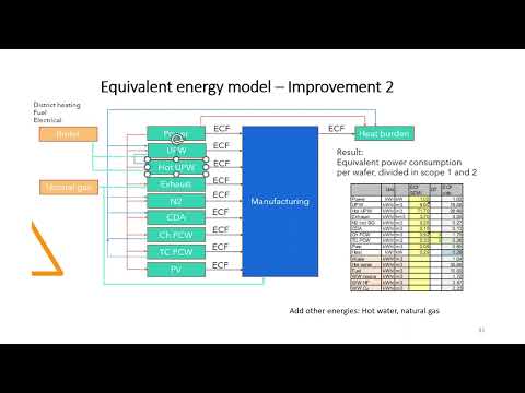
2. The approach towards the relationship between H-UPW and energy has evolved The original approach taken in SEMI S23 (Guide for Conservation of Energy, Utilities and Materials Used by Semiconductor Manufacturing Equipment) focused only on power consumption as it related to the tool, and services to and from the tool. Since then, the International Roadmap for Devices and Systems (IRDS) has made different revisions to the Energy Equivalent Model. Latest models consider the energy consumption of all facility utility systems and heating loads (boilers, district heating/cooling and natural gas).
McIntosh used an example H-UPW system to show how different models result in different energy usage calculations. In this example:
- With the original SEMI S23 model, 9.0 kWh/m3 of energy is consumed.
- With the IRDS latest revision Energy Equivalent model, 18.1 kWh/m3 of energy is consumed.
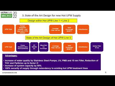
3. Finding opportunities for reducing H-UPW usage and energy impact is difficult. H-UPW is needed in the manufacturing process in precise amounts and temperatures at intermittent periods of high and low demand. In addition, ever-tightening process requirements for the purity and temperature of H-UPW means that any changes to traditional systems must deal with the challenge of maintaining these parameters. The strict temperature and purity requirements are also driving up the volume of H-UPW which is bypassed, as higher volumes are needed for minimum flows which run across the tool to prevent contamination and maintain temperatures.
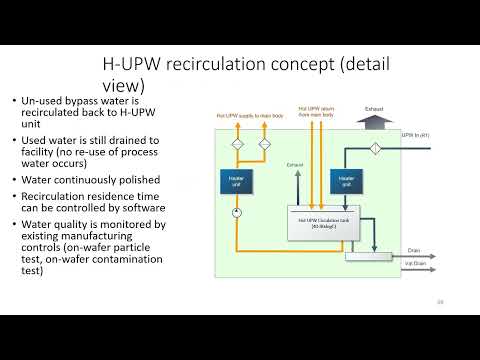
4. Recirculation of H-UPW can save energy and water in the tool environment Miller demonstrates that installing a pump and a H-UPW circulation tank can recapture bypass water and recirculate it without allowing it to cool down. This method has additional benefits as it reduces fluctuations in UPW temperature deriving from the facility and reduces the pressure to limit minimum bypass flows. As such, better temperature control can be achieved within the tool.
This method does not recycle water used in the manufacturing process – any water which has been directly used will go to the drain. For more details and data, please view the recording Conserving energy and water through recapture and recirculation of hot UPW by Charles Miller, SCREEN SPE.
5. Approaching overall system design differently can provide opportunities for heat recovery In a conventional H-UPW system, some heat may be recovered from H-UPW loop as the water returns, but no heat will be recovered from any H-UPW used in the process – and that will simply be sent down the drain. Furthermore, any water which is discharged must be cooled for safety reasons, and the cooling process also consumes energy.
McIntosh demonstrates that it is possible to optimize system design by installing a tank to hold and maintain the temperature of the H-UPW rather than sending it back through the full H-UPW loop. The H-UPW can be polished again through an ultrafilter before being sent to the manufacturing process again. In this circumstance, only small quantities of heat will be lost from the water, and it reduces the volume of water which must be cooled. Another tank can be installed to capture water from the process drain, from which heat can be recovered when it is pumped back to a heat exchanger.
For more details and data, view the recording Eco-efficiency in ultrapure water system design and operation by Bob McIntosh, Enviro-Energy Solutions and Andreas Neuber, Applied Materials.
Share this insight
Related insights
5 key UPMU workshop takeaways: UPW system design principles

Georgia Bottomley
Global Water Intelligence
Q&A Results with ElectraMet: Copper recovery from CuCMP Wastewater

Cameron Lippert
Electramet
The Rising Tide of CEDI: Why it is Outshining Traditional Ion Exchange in High-Purity Applications (Part 2)

Orla McCoy
Global Water Intelligence
Related resources
Conserving energy and water through recapture and recirculation of hot UPW
Eco-efficiency in ultrapure water treatment system design and operation